
MBR hollow-fibre membranes
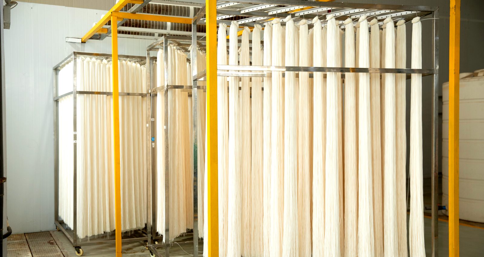
Curtain elements for the biological stage — 10, 21 and 32 m², a 0.025 µm PVDF skin, forty-eight to a stainless cassette. In a membrane bioreactor the membrane does not treat the feed. It sits in the aeration tank and holds the biomass there while clear water leaves.
What MBR duty actually asks for
The feed has already been through biology. What reaches the membrane is mixed liquor — water, dissolved matter, and a few grams per litre of sludge floc that has to stay in the tank. Three things follow from that:
- Solids are low and uniform. Mixed liquor typically runs 6–12 g/L, and the floc is soft rather than abrasive.
- Fouling is controlled by air, not by crossflow. Coarse bubbles rising past the fibre bundle scour the surface. There is no recirculation pump doing the work.
- Flux is low and area is large. These elements are quoted at 10–30 L/m²·h, an order of magnitude below a tubular loop. The plant pays for area, so packing density decides the capital cost.
The pore is 0.025 µm. The membrane is not there to remove dissolved species — it is there to keep the biomass out of the permeate.
Three element sizes, one fibre
A curtain element is a header, a potted root block and a bundle of fibre hanging off it. The three sizes differ only in how much fibre hangs there — the fibre, the potting and the operating envelope are the same across all three.
| Item | MP-LR10-M | MP-LR21-J | MP-LR32-J |
|---|---|---|---|
| Membrane area | 10 m² | 21 m² | 32 m² |
| Element size A×B×C | 660×1500×40 mm | 875×1460×58 mm | 875×2160×58 mm |
| Wet weight | 10 kg | 20 kg | 30 kg |
| Fibre bore / outside diameter | 0.8 / 2.1 mm | ||
| Nominal pore | 0.025 µm | ||
| Fibre material | PVDF, asymmetric | ||
| Potting | Polyurethane | ||
| Flow mode | Outside-in | ||
| Design flux | 10–30 L/m²·h | ||
| Operating pH | 5–9.5 | ||
| Cleaning pH | 2–10.5 below 30 °C · 2–10 at 30–40 °C | ||
| Transmembrane pressure | −55 to +55 kPa | ||
| Chlorine tolerance | 5,000 mg/L | ||
| Permeate turbidity | ≤0.2 NTU | ||
| Permeate SDI15 | ≤3 | ||
The −55 to +55 kPa band is the working envelope in both directions: suction during filtration, push during backwash. Elements are stored and shipped wet, and stay wet in service.
The support layer under the skin is what carries the pressure
The fibre is cast in one pass by the VNIPS process into a single asymmetric structure: a dense separation skin on the outside, an open sponge behind it, and a high-strength support layer taking the wall loads. Water runs outside-in — across the skin, through the sponge, out through the bore.
- Burst pressure above 0.6 MPa. The skin is anchored into the support layer rather than laid on top of it, so it does not delaminate when the element is backwashed hard or air-scoured for years.
- The roots are combed, not bunched. Each fibre is laid in order where it enters the header. Sludge that reaches the root passes through instead of packing into a mat, which is the usual way a curtain element loses its bottom third.
- Built for dirty water. A 0.8 mm bore will not pass rags or grit, so this element belongs after screening — but it is aimed at streams where a fine-bore fibre would cake over in weeks.
Pore size is uniform across the skin by design. That is what makes the turbidity figure repeatable rather than a best case.
Forty-eight elements to a cassette
Elements are not installed one at a time. They hang in a stainless cassette that carries the permeate header and the aeration header, and the cassette is the unit that gets lifted out for cleaning or replacement.
| Cassette | Data |
|---|---|
| Elements per cassette | 48 standard — the count can be reduced without changing the frame |
| Cassette size L×W×H | 1860×2020×1500 mm · 1860×2020×2500 mm |
| Frame material | 316L / 304 stainless steel |
| Permeate outlet | DN100, DN80 |
| Air header | 2 × 3″ UPVC |
| Maximum air temperature | 65 °C |
| Instantaneous aeration | 8–15 times the design permeate flow |
| Aerator head loss | 0.05 bar, excluding hydraulic loss |
Where a hollow fibre is the right call
Put simply: when the solids are low enough that the channel will not plug, the denser geometry wins. That covers most municipal and light-industrial MBR duty.
Footprint is tight
A fibre bundle delivers several times the membrane area of the same volume of tubes. When the tank volume is fixed by civil works you have already built, that ratio decides whether the duty is feasible at all.
Solids are predictable
Mixed liquor from a well-run biological stage is a known quantity. If the upstream process is stable and screened, the fibre bundle sees a feed it can handle for years.
Permeate quality drives the train
For reuse, or for a downstream RO stage, the low turbidity and stable SDI off an MBR often remove a whole treatment step further down the line.
Where it is not
A hollow fibre is a filter with a very small mouth. Anything that arrives in slugs, that carries oil, or that cannot be dissolved by chemicals will eventually close it — and a closed fibre bundle cannot be rodded out the way a tube can.
What we need to size one
An MBR is sized on flux and solids, not on pore size. Six numbers get you to a first-pass design:
| Input | Why it changes the answer |
|---|---|
| Design flow, m³/d | Sets the membrane area at the chosen flux. State whether it is average or peak. |
| MLSS, g/L | The single most important number. It sets both the fouling rate and the aeration demand. |
| Peak factor | Storm or batch discharge can double the instantaneous flow. Area is sized on the peak, not the average. |
| Temperature range | Cold mixed liquor is more viscous and fluxes lower. A winter minimum changes the area. |
| Permeate target | Whether the permeate goes to discharge, to reuse, or straight into an RO stage. |
| Tank volume available | Decides the cassette count that will physically fit, which can override the calculated area. |
Send these six and we will come back with a cassette count, an aeration estimate and a cleaning regime — not a catalogue page.
The same fibre, in a pressure housing
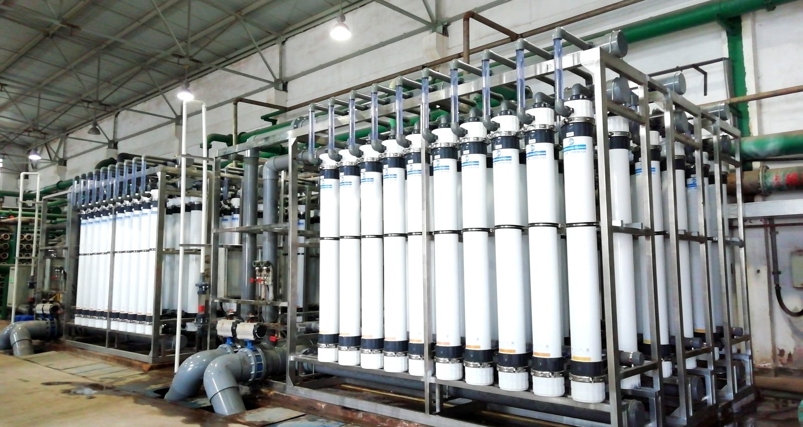
Not every dirty-water duty wants a tank. Where the stream is already clarified — secondary effluent, filter backwash, surface water — the same fibre goes into a UPVC pressure housing and runs dead-end or in crossflow. Solids are lower, so the flux is roughly four times higher and the footprint is a skid rather than a basin.
| Item | DW-ZU0880-B | DW-ZU0860-B | DW-ZU0660 |
|---|---|---|---|
| Membrane area | 75 m² | 50 m² | 40 m² |
| Housing size | Φ225×2360 mm | Φ225×1860 mm | Φ160×1775 mm |
| Wet weight | 65 kg | 53 kg | 35 kg |
| Ports, in / permeate / concentrate | DN50 / DN50 / DN50 | DN50 / DN50 / DN50 | DN40 / DN40 / DN32–40 |
| Flux | 60–120 L/m²·h | ||
| Maximum transmembrane pressure | 0.20 MPa | ||
| Maximum backwash pressure | 0.25 MPa | ||
| pH range | 2–12 | ||
| Operating temperature | 1–40 °C | ||
| Shell / potting | UPVC, food grade / epoxy resin | ||
| Chlorine tolerance | 5,000 mg/L | ||
| Permeate turbidity / SDI15 | <0.1 NTU / <2.5 | ||
Same 0.025 µm fibre, same chlorine tolerance, wider pH band because there is no biology to protect. Runs dead-end with periodic backwash, or in crossflow where the suspended load justifies it.
Three ways to separate the same water
| Item | Submerged MBR | Pressure-housing UF | Tubular UF |
|---|---|---|---|
| Feed | Mixed liquor, 6–12 g/L | Clarified secondary effluent | Up to several percent, slurries and sludge |
| Driving force | Suction, −55 to +55 kPa | 0.20 MPa transmembrane | 3–5 m/s crossflow |
| Flux | 10–30 L/m²·h | 60–120 L/m²·h | 60–120 L/m²·h |
| Fouling control | Coarse-bubble aeration at 8–15× permeate flow | Backwash and chemical clean | Crossflow shear, mechanical cleaning |
| Area per unit volume | Highest | High | Lowest |
| Oil, rags, grit | Poor | Fair | Good — the open channel passes them |
| Where it belongs | Biological stage, reuse pre-treatment | Polishing ahead of RO | High-solids effluent, leachate, oily water, softening |
All three separate on the same principle. The difference is what each one can be fed, and what it costs to keep it clean.
Tell us the solids and the flow, and we will tell you which one to look at.
If the answer is tubular, we will say so. All three configurations are built here.
Send your duty Request a pilot