
Leachate: the solids decide the outcome, not the COD
Leachate is the stream that finishes off a spiral-wound module — suspended solids, high organics, calcium scaling and a pH that moves. That is why channel width, not pore size, is the first decision here, and why the membrane belongs behind the biology and in front of NF or RO rather than instead of either.
Four properties decide the outcome
Solids that change with the site's age
Refuse composition, cover and rainfall all move the solids load. The number measured last year is not this year's number, and a membrane sized to the average plugs on the peak.
Scaling potential
Calcium, magnesium, carbonate and sulphate are what stop a reverse-osmosis stage short of its recovery target. Ultrafiltration does not remove them in solution — it removes what would seed them.
Salinity
Chloride and TDS pass straight through. They are the reason a leachate train cannot be closed by membrane alone, and the reason the RO behind the UF has a concentrate to deal with.
What the bio-tank leaves
The membrane sits behind the biological stage, so its duty is defined by what the biology already achieved. That is a number to measure, not to assume.
It does not remove dissolved COD, ammonia, chloride or TDS. Leachate permeate from a UF still fails a discharge limit on those. The membrane protects the stage behind it and returns solids to the biology — if the target is a limit on COD or ammonia, that is a biological or an oxidation problem. Saying so at the start is cheaper than discovering it at commissioning.
Where a tubular UF earns its place in the train
1 · Between the bio-tank and NF/RO
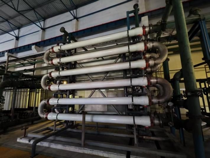
The standard route on our leachate references: biological treatment first, tubular UF next, then NF or RO. The concentrate returns to the bio-tank, so solids do not build up inside the element.
2 · Instead of a clarifier and sand filters
The same duty in less footprint, and the reject goes back to the biology rather than becoming sludge that has to be dewatered and hauled away.
3 · Ahead of the evaporator
Where the site runs a thermal stage, taking the solids out first cuts the volume that has to be boiled and the fouling that has to be cleaned off it.
The biological stage, or the NF/RO behind it. A membrane that removes solids and nothing else will not turn leachate into discharge-quality water on its own.
Why channel width comes before pore size here
Five open channel diameters. On leachate the choice is driven by peak solids and by how much they move as the site ages — not by the pore size.
| Channel | When it is the right choice |
|---|---|
| 6 mm | Polishing an already clean permeate, downstream of an existing clarifier. Not the choice where grit is present. |
| 8 / 10 mm | The common middle. Most leachate polishing duties land here, and it is where most of our leachate references run. |
| 12.7 mm | Where peak solids are higher, or where the biology carries more sludge than the clarifier was designed for. |
| 25 mm | For streams that plug anything smaller. The widest channel we make; it belongs in the specification, not in the headline. |
What "mechanically cleanable" means on leachate
The foulant here is a mix of biological slime and carbonate scale, and neither comes off with backwash alone. Cleaning is done by pushing sponge balls through the channel and alternating acid with hypochlorite, so the element returns to flux instead of being written off.
Four numbers decide whether it works — none is on a datasheet
Ask these of the site before anything is sized:
- Peak suspended solids, and the swing between wet and dry season
- Hardness and sulphate — the two that decide how far the RO behind it can go
- Site age, and the trend in the BOD/COD ratio rather than today's value
- What the bio-tank already achieves, and whether it holds that figure
These four are why we do not publish a design flux for leachate. A number that is right for a five-year-old site is wrong for a fifteen-year-old one.
Five leachate references, 1,280 m³/d combined
These are commissioned installations, not projections. Client names are withheld; location and design capacity are given so that any of them can be discussed in detail under NDA.
| Location | Membrane stage | Configuration |
|---|---|---|
| Shandong | 480 m³/d | Tubular UF |
| Anhui | 250 m³/d | Tubular UF |
| Henan | 200 m³/d | Tubular UF |
| Jiangxi | 200 m³/d | Tubular UF |
| Xinjiang | 150 m³/d | Tubular UF |
Capacities are the design figure for the membrane stage. Actual throughput follows the feed and the operating regime.
The hardest one: leachate from a waste-incineration plant
Incineration leachate carries higher suspended solids, higher organics and a pH that moves further than a municipal landfill's. The configuration is the same one used in the table above: bio-tank, tubular UF, then NF or RO, with the concentrate returning to the bio-tank.
How a leachate project runs
Every installation above went through the same sequence before any hardware was built. This is the part that is usually skipped, and it is the part that decides whether the plant holds its flux.
1 · Sample and analysis
Feed sample taken on site and analysed for solids, oil, hardness, salinity and particle size distribution.
2 · Bench, then pilot
Bench test on your sample, then a pilot on your own stream. Flux, cleaning interval and recovery are measured rather than assumed.
3 · Design and commissioning
Sizing, element selection and arrangement drawings, then commissioning support and follow-up service.
If the numbers say the membrane is the wrong tool for your feed, we say so before you commit to hardware.
Send your feed data
The useful starting point is not a flow rate, it is a water analysis. Send solids, hardness, salinity and the target you have to meet, and we will tell you which of the five configurations above is closest to your stream.
Common questions
No. It removes no dissolved organics and produces no biogas. It sits behind the biology and protects what comes after it.
Not for COD, ammonia or chloride — those are dissolved and pass through. Where the limit being missed is on suspended solids, a membrane helps directly. Where it is on COD or ammonia, the biological or oxidation stage has to carry it.
A spiral-wound element needs pre-filtration to roughly 100 micrometres and packs the solids into a spacer that cannot be brushed out, so on leachate it blinds. An MBR is a biological process with the membrane inside the tank — a different duty, and it does not solve a solids-and-scaling problem downstream of the biology.
That is a pilot number, not a catalogue number. It depends on the calcium and the solids in your feed, and measuring it is one of the things the pilot is run for.
More on this: Selection guide · Tubular UF · Operating projects · Pilot testing