
Four membrane lines, one design principle
The channel is the product. When a feed carries solids, oil or scale-forming salts, the deciding factor is rarely the pore size — it is whether the geometry lets the stream through and lets you clean it afterwards.
Tubular ultrafiltration
Organic tubular membranes with an open inner channel, run in crossflow. Built for streams that would blind a hollow-fibre module.
- Channel diameters of 8 mm and 5.2 mm
- Nominal pore size 0.03 µm
- Inside-out (inner-pressure) crossflow operation
- Mechanically cleanable — not backwash-only
TMF softening membrane
Chemical softening coupled with membrane separation in one step, with continuous sludge concentration and discharge.
- Softening and separation in a single stage
- Continuous sludge concentration and discharge
- Removes hardness ahead of a high-recovery RO train
- Reported operating window of 3%–5% solids — to be confirmed against your feed
Open-channel reverse osmosis
Disc-tube and net-tube RO elements with an open feed channel, designed for high-salinity and high-recovery duty.
- Open channel resists scaling and particulate fouling
- Suited to high-salinity and high-recovery duty
- Handles the concentrate stage where spiral-wound elements foul out
- Flux and pressure to be confirmed per project
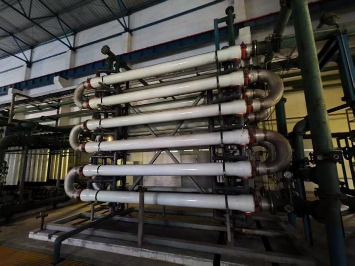
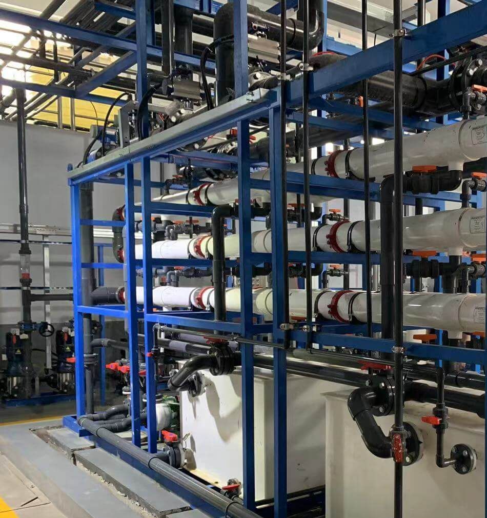
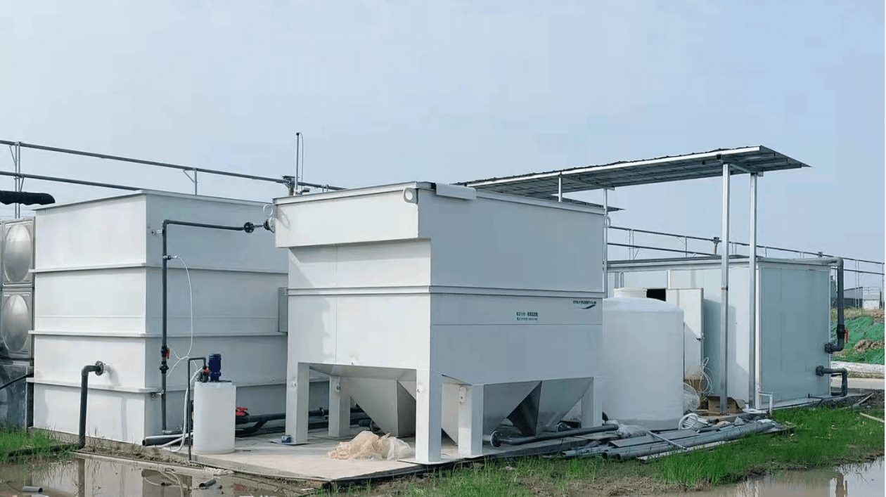
Arrangement drawings
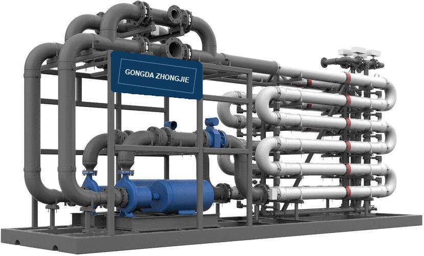
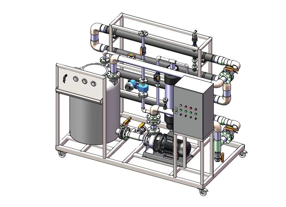
Hollow-fibre ultrafiltration for conventional low-solids duty — the right choice, and the cheaper one, whenever the feed allows it. We will tell you when it does. See the selection guide for where each configuration stops making sense.
Solids ceiling by membrane configuration
Hollow-fibre UF is typically specified up to about 1% suspended solids (roughly 10 g/L). Between 1% and 3%, either configuration can work, and the deciding factors are viscosity, particle size distribution and oil content. Above roughly 3% solids, tubular configurations are the practical choice: the open channel tolerates the solids load and can be cleaned mechanically rather than by backwash alone.
Rule of thumb from field experience. Confirm against your own feed data before sizing.
| Feed condition | Practical starting point | Why |
|---|---|---|
| TSS ≤ ~1% (≈10 g/L) | Hollow-fibre UF | Highest packing density, lowest cost per m² of membrane area |
| TSS ~1–3% | Either — decide on viscosity, PSD, oil | Both can work; a pilot decides, not a catalogue |
| TSS > ~3% | Tubular UF | Open channel tolerates solids; mechanically cleanable |
| Oily or emulsified feed | Tubular UF | Wall shear keeps oil moving; oil blinds hollow fibre and resists backwash |
| High salinity, high recovery | STRO / DTRO | Open disc-tube channel resists scaling and fouling |
| Hardness, chemical softening | TMF | Softening coupled with separation; continuous sludge discharge |
Figures above are starting points for discussion, not a specification. Final selection follows a pilot on your feed.
Every element carries a part number you can read
No decoding table needed and no sales call to find out what a code means. Seven fields describe the whole element: channel bore sets the solids tolerance, outside diameter and length set the membrane area, and the housing material sets the corrosion and pressure class.
TM = tubular MF
Worked example — GDZJ-TUF-8830-F: tubular UF, PVDF-class membrane, 8 mm bore, 8 inch element, 3 m long, FRP housing.
Full field list, housing options and component dimensions: model code & specifications
A membrane maker, not a trading house
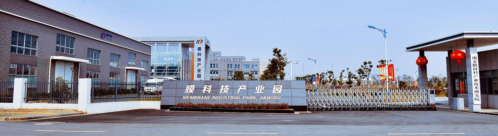
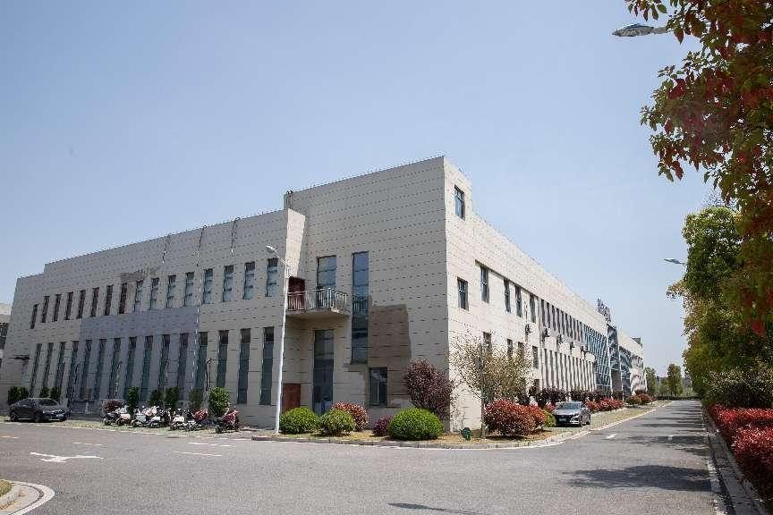
Jiangsu Zhongjie Environmental Technology Co., Ltd. was founded in 2014 and works out of the membrane technology industrial park in Jiangbei New Area, Nanjing. The membrane material, the welded tubular element and the assembled skid are produced and tested on the same site, which is why we can tell you what a stream will do before you commit to a plant.
Technical development is tied to the membrane science research institute at Nanjing Tech University. That link is the source of the material formulations and of the element structures we weld — and of the multi-year element life that follows from them.
Ten commissioned plants, 3,220 m³/d combined
Not one showcase plant. The same element sized against five different duties, with the route used in each — so a buyer can find the case closest to their own stream.
| Duty | Projects | Capacity | Route |
|---|---|---|---|
| Landfill leachate | 5 | 1,280 m³/d | Pre-screen → tubular UF → concentrate handling |
| Softening ahead of RO | 1 | 1,000 m³/d | Chemical softening and membrane separation in one stage |
| Plant extraction | 2 | 390 m³/d | Tubular UF for clarification and concentration |
| Municipal wastewater | 1 | 400 m³/d | External tubular UF on the biological stage |
| Titanium dioxide effluent | 1 | 150 m³/d | Conditioning → tubular UF → further treatment |
Locations, capacities and the full route for each project: commissioned projects & application scenarios
Pilot first, quote second
Most membrane projects do not fail because of the membrane. They fail because the feed was never understood — a clean average sample, taken on a good day, standing in for a stream that spikes on Tuesdays.
Feed data, not a wishlist
We start from the numbers that actually size a membrane: peak solids as well as average, oil and solvent load, salinity, temperature range, and the worst hour the plant has seen rather than the design point.
A pilot skid, on your stream
Where the feed is uncertain, the answer comes from a trial rather than a datasheet. We run a pilot on the real stream so that flux, cleaning interval and recovery are measured, not assumed.
A quotation you can defend
The commercial offer is built on measured performance, so the numbers in it are ones you can take to your own client without a caveat attached.
Tell us three numbers
Peak TSS, oil content and salinity are enough for us to tell you which configuration to look at first — and whether hollow fibre would do the job for less money.
Send your feed dataStated plainly, so nobody is surprised later
Ultrafiltration operates in the 0.01–0.1 µm range. Arsenic, iron and manganese in true solution, hardness ions and most of the dissolved organic fraction pass straight through. If those are the target, UF is a pre-treatment step, not the answer — the removal step has to be oxidation, adsorption, ion exchange or reverse osmosis, depending on the species.
Membrane selection and process selection are two different decisions. We are happy to tell you when the second one does not involve us.